Friday, February 26, 2016

RATE ANALYSIS OF PLASTERING WITH CEMENT MORTAR

Rate analysis of plastering with cement mortar requires the quantity estimation of materials cement mortar, i.e. quantity of cement, sand and water for various grades of mortar required. Grades of mortar used for plastering is generally same grade as used in the masonry work.
There are different grades of mortar that can be used for plastering of masonry structural members such as in CM 1:2, 1:4, 1:6, 1:8 etc. Cement Mortar in ratio 1:6 is generally used for plastering work.
For the calculation of quantity of cement and sand in mortar, volume of mortar required for plastering is calculated based on thickness of plastering surface and surface area of the structural member.
rate-analysis-of-plastering-with-cement-mortar
Let us take an example of a wall to be plastered:
Length of wall = 2m
Width of wall = 1.5m
Thickness of plaster to be used = 20mm
Plaster to be carried out in two layers of 10mm each.
The quantity of cement mortar required will be: 2 x 1.5 x (20/1000) = 0.06 m3 of mortar.
The rate analysis of mortar need to be done for the calculated quantity required. Read here the rate analysis of cement mortar to know how to calculate quantity of cement and sand in mortar.
Once the quantity of cement and sand is calculated, the labor cost required for mixing of mortar is calculated. The coefficients of labor for plastering work are taken from the Rate Analysis by CPWD.
The cost of mixing of calculated quantity of mortar remains constant, but the cost of application of mortar varies with number of layers in which the mortar is applied. Thus, the cost of mason depends on area to be plastered and number of layers of plaster to be applied. The cost of other labors varies with the quantity of cement mortar to be mixed and number of layers of plasters to be applied.
The coefficients of mason and labors are as follows per m2 area per layer of plaster to be applied:
Mason – 0.07435 days
Labors – 0.0929 days
Bhishti – 0.0929 days (the one who carries materials and water for mixing)
These coefficients are multiplied with the given quantity of cement mortar required for plaster in m3 and number of layers or plasters.
The number of days of mason required = 0.07435 x No. of layers x surface area
= 0.07435 x 2 x (2 x1.5) = 0.44610 days
For Labors and Bhishti = 0.0929 x 2 x (2 x 1.5) = 0.5574 days for each.
The labor and bhishti days required for mixing of cement mortar is also calculated as given in rate analysis of cement mortar.
For example, labor required = 0.21 x 0.06 = 0.0126 days
Bhishti required = 0.0929 x 0.06 = 0.005574 days.
Thus total number of days for plastering in two-layers of plaster for 1.5mx2mx20mm plaster:
Mason = 0.44610 days
Labor = 0.5574 + 0.0126 = 0.57 days
Bhishti = 0.5574 + 0.005574 = 0.562974 days.
The daily wages of masons and labors are multiplied with number of days required by them to get the cost.
The excel calculation for rate analysis of plastering is shown below:
 <p>Your browser does not support iframes.</p><p>


RATE ANALYSIS FOR PLATERING
Write your currency
Length of plaster
m
Height of plaster
m
Thickness of plaster
mm
Number of Layers
Surface area
m2
Mortar Ratio  1 :
Dry Mortar Required 
m3
MATERIAL incl. transport Qty. Unit Rate Cost
Cement Bags
Bags
Sand 
m3
LABOUR  Days Rate Cost
Mason 
Labour 
Bhishti 
PRIME COST (Rs.):
Scafolding @ 1 % of the prime cost
Water Charges @2% of Prime cost
SUNDRIES @ 5% of cost of Labour+Material
CONTRACTOR PROFIT
%
TOTAL COST =

TYPICAL CONSTRUCTION JOINTS IN BEAMS AND COLUMNS


Construction joints are required when the concreting has to be stopped for the day or more than 30minutes. In such case, typical construction joints shall be provided so that bond is maintained between set concrete and fresh concrete. Below are some images showing correct method of construction joints to be provided in columns, beams and beam-column junction. To know about what is construction joint, read Joints in Concrete Construction.

1. Construction Joint in Column

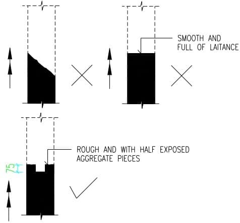
Following figure shows correct method of providing construction joint in column. Construction joint in column shall not be provided with smooth surface or inclined surface. The top surface of the column should be rough with parts of coarse aggregates being seen.
construction-joints-in-column
Fig: Typical Construction Joint in RCC Column

2. Construction Joint in Beams and Beam-Column Joint:

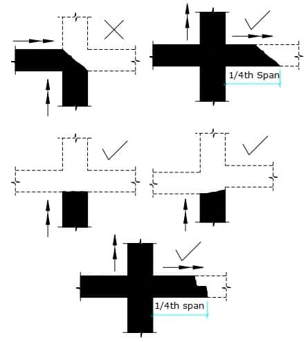
Following figure shows the typical construction joint to be provided in beams and beam column joints.
Construction Joint in Beams and Beam-Column Joint
Fig: Typical Construction Joint in Beams and Beam-Column Joint
The arrow symbol shows the direction of concreting, tick mark shows the correct method of providing construction joint while cross-mark shows the wrong method.

Construction Technology::All about civil construction.: MIX DESIGN OF HIGH STRENGTH CONCRETE

Construction Technology::All about civil construction.: MIX DESIGN OF HIGH STRENGTH CONCRETE: The properties of a high-strength concrete-mix with a compressive strength of more than 40 MPa is greatly influenced by the properties of...

MIX DESIGN OF HIGH STRENGTH CONCRETE

The properties of a high-strength concrete-mix with a compressive strength of more than 40 MPa is greatly influenced by the properties of aggregates in addition to that of the water-cement ratio. To achieve high strength, it is necessary to use lowest possible water-cement ratio, which invariably affects the workability of the mix and necessitates the use of special vibration techniques for proper compaction. In the present state of art, a concrete with a desired 28 day compressive strength of upto 70 MPa can be made with suitably proportioning the ingredients using normal vibration techniques for compacting the concrete mix.
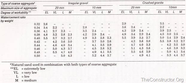
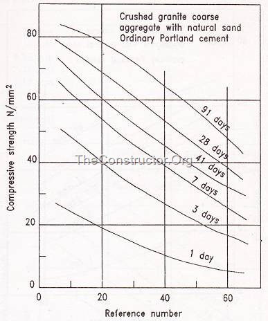
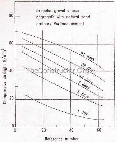
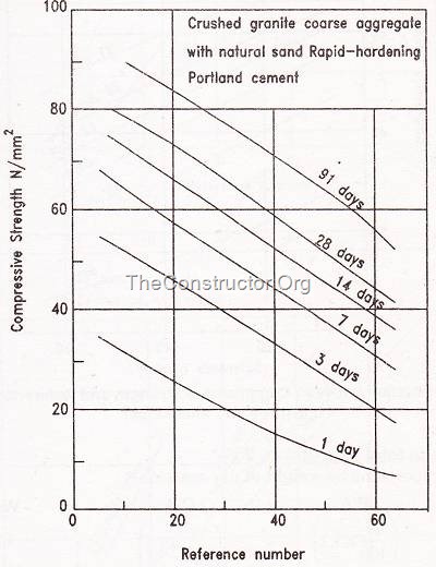
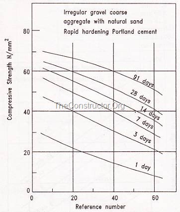
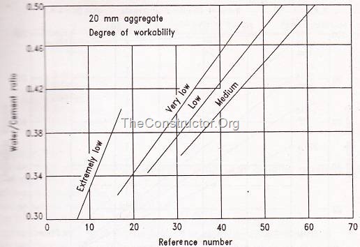
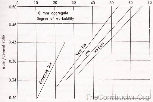
Erntroy and Shacklock’s Empirical Graphs: Erntroy and Shacklock have suggested empirical graphs relating the compressive strength to an arbitrary ‘reference number’ for concrete made with crushed granite, coarse aggregates and irregular gravel. These graphs are shown in figure 1 and 2 for mixes with ordinary Portland cement and in figure 3 and 4 for mixes with rapid hardening Portland cement. The relation between water cement ratio and the reference number for 20mm and 10mm maximum size aggregates is shown in figure 5, in which four different degrees of workability are considered. The range of the degrees of workability varying from extremely low to high corresponds to the compacting factor values of 0.65 and 0.95 respectively
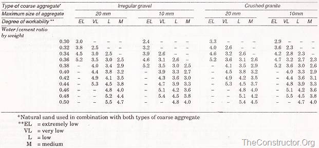
The relation between the aggregate-cement and water-cement ratios, to achieve the desired degree of workability with a given type and maximum size of aggregate are compiled in table-1 and 2 for two different types of cements. The limitations of these design tables being that they were obtained with aggregates containing 30 percent of the material passing the 4.75 mm IS sieve. Thus, if other ingredients are used suitable adjustments have to be made. Aggregates available at site may be suitably combined by the graphical method to satisfy the above requirement. In view of the considerable variations in the properties of aggregates, it is generally recommended that trial mixes must first be made and suitable adjustments in grading and mix proportions effected to achieve the desired results.
Table – 1: Aggregate cement ratio (by weight) required to give four degrees of workability with different water –cement ratios using ordinary Portland cement
Aggregate cement ratio (by weight) required to give four degrees of workability with different water –cement ratios using ordinary Portland cement
Table – 2: Aggregate cement ratio (by weight) required to give four degrees of workability with different water –cement ratios using rapid hardening cement
Aggregate cement ratio (by weight) required to give four degrees of workability with different water –cement ratios using rapid hardening cement
MIX DESIGN PROCEDURE:
  1. The mean design strength is obtained by applying suitable control factors to the specified minimum strength.
  2. For a given type of cement and aggregates used, the reference number corresponding to the design strength at a particular age is interpolated from figure 1 to 4.
  3. The water-cement ratio to achieve the required workability and corresponding to the reference number is obtained from figure 5 for aggregates with maximum sizes of 20mm and 10mm.
  4. The aggregate-cement ratio to give the desired workability with the known water cement is obtained by absolute volume method.
  5. Batch quantities are worked out after adjustments for moisture content in the aggregates.
Relation between compressive strength and reference number (Erntroy and Shacklock)
Fig.1: Relation between compressive strength and reference number (Erntroy and Shacklock)
Relation between compressive strength and reference number (Erntroy and Shacklock)
Fig-2: between compressive strength and reference number (Erntroy and Shacklock)
Relation between compressive strength and reference number (Erntroy and Shacklock)
Fig-3: Relation between compressive strength and reference number (Erntroy and Shacklock)
Relation between compressive strength and reference number (Erntroy and Shacklock)
Fig-4: Relation between compressive strength and reference number (Erntroy and Shacklock)
Relation between water-cement ratio and Reference Number
Fig-5: Relation between water-cement ratio and Reference Number
Combining of Fine aggregates and Coarse aggregates
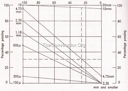
Fig-6: Combining of Fine aggregates and Coarse aggregates
Table – 3: Batch Quantities per cubic metre of concrete
Batch Quantities per cubic metre of concrete
MIX DESIGN EXAMPLE
Design a high strength concrete for use in the production of precast prestressed concrete to suit the following requirements:
Specified 28-day works cube strength = 50 MPa
Very good degree of control; control factor = 0.80
Degree of workability = very low
Type of cement = ordinary Portland cement
Type of coarse aggregate = crushed granite (angular) of maximum size 10mm.
Type of fine aggregate = natural sand
Specific gravity of sand = 2.60
Specific gravity of cement = 3.15
Specific gravity of coarse aggregates = 2.50
Fine and coarse aggregates contain 5 and 1 percent moisture respectively and have grading characteristics as detailed as follows:

IS sieve size
Percentage Passing
Coarse aggregate
Fine aggregate
20mm
100
10mm
96
100
4.75mm
8
98
2.36mm
80
1.18mm
65
600 micron
50
300 micron
 
10
150 micron
0

DESIGN OF MIX
Mean strength = (50 / 0.80) = 63 MPa
Reference number (fig.1)= 25
Water cement ratio (fig 5) = 0.35
For a 10mm maximum size aggregate and very low workability, the aggregate-cement ratio for the desired workability (table-1) =3.2
The aggregates are combined by the graphical method as shown in figure 6, so that 30 percent of the material passes through the 4.75 mm IS sieve.
Ratio of fine to total aggregate = 25%
Required proportions by weight of dry materials:
Cement – 1
Fine aggregates – [(25/100)x3.2] = 0.8
Coarse aggregates – [(75/100)x3.2)] = 2.4
Water = 0.35
If C = weight of cement required per cubic meter of concrete, then
clip_image011
clip_image012

ACI METHOD OF CONCRETE MIX DESIGN

ACI method of concrete mix design is based on the estimated weight of the concrete per unit volume. This method takes into consideration the requirements for consistency, workability, strength and durability.

Following are the steps of ACI Method of Concrete Mix Design:

ACI Method of Concrete Mix Design
(a) Depending on the degree of workability and placing condition determine the slump value.
(b) Depending on the economical availability and dimensions of the structure determine the maximum size of aggregate.
(c) For the given slump and maximum size of coarse aggregate determine the amount of mixing water.
(d) Determine the minimum water-cement ratio either from strength considerations or from durability considerations.
(e) Determine the amount of cement per unit volume of concrete from steps (c) and (d). This cement content should not be less than the cement content required based on durability criteria.
(f) Determine the amount of coarse aggregate required for a unit volume of concrete. This value is multiplied by the dry rodded unit weight of the aggregate to get the required dry weight.
(g) Determine the amount of fine aggregate. If the weight of concrete per unit volume is assumed, the required weight of fine aggregate is obtained by the difference between the weight of fresh concrete and the total weight of all other ingredients. The weight of fresh concrete may be estimated by using following equation:
ACI Method of Concrete Mix Design
Where,
= weight of fresh concrete in kg/m3
= weighted average specific gravity of combined fine and coarse sand,
= specific gravity of cement = 3.15
= cement requirement in kg/m3
= mixing water requirement in kg/m3
A = Air content in percent.
(h) Adjust the mixing water quantity on the moisture content in the aggregate.
(i) Check the calculated mix proportions by trial batches prepared and tested in accordance with the IS specifications and make another trial if required.

TESTS ON WATER FOR CONCRETE

TESTS ON WATER FOR CONCRETE

A simple way of determining the suitability of water for mixing is to compare the setting time of cement and the strength of mortar cubes using the water in question with the corresponding results obtained using de-ionized or distilled water. The initial setting time should not be less than 1 hour and to be within 25% of the result with distilled water. Final setting time shall not exceed 12 hours and also be within 25% with the distilled water. The mean strength should be atleast 90 per cent of that obtained with distilled water. Those requirements may be compared with BS 3146: 1980, which suggests a tolerance of 30 min in the initial setting time and recommends a tolerance of 10 per cent for strength. The ASTM C 1602 – 06 requirement for setting time is from 1 hour early to 1 hour 30min later, while strength has to be at least 90 per cent.

tests on water in concrete

Whether or not staining will occur due to impurities in the curing water cannot be determined on the basis of chemical analysis and should be checked by a performance test involving simulated wetting and evaporation.

Construction Technology::All about civil construction.: ESTIMATING LIFE OF RESIDENTIAL BUILDING

Construction Technology::All about civil construction.: ESTIMATING LIFE OF RESIDENTIAL BUILDING: There are different methods of estimating the life of a building. This can be done by carrying out health check up of the building. Depe...

ESTIMATING LIFE OF RESIDENTIAL BUILDING

There are different methods of estimating the life of a building. This can be done by carrying out health check up of the building. Depending on the degree of sophistication and desired accuracy level vis-a-vis the problem in hand ,there are many equipment and methodologies available to evaluate the probable life of a structure. Many times a thorough visual inspection reveals the distress and the causes.

residential-building
Equipments used for HEALTH CHECK UP of the building are:

REBOUND HAMMER: It senses the soundness of concrete up to a marginal depth.

IMPACT ECHO TESTER: Finds out defects in the interior of concrete.

ULTRASONIC TESTERS: Scans through the concrete for the full depth/thickness.

COVER METER: Finds out the cover to the reinforcement (steel bars inside the concrete).

PROFOMETER: Establishes configuration and quantum of interior reinforcements (steel bars inside the concrete)

REBAR PHOTOGRAPHER: Displays interior reinforcements (steel bars) skeleton.

ENDOSCOPIC DEVICE: To examine the void in the concrete.

THERMOGRAPHIC CAMERA: To locate possible defect in a new building.

CRACK MEASUREMENT DEVICE: It measures surface cracks.

PERMEABILITY TESTER: Tests for water penetration in concrete.

THICKNESS GAUGE: Measures the thickness from the surface.

LEAK SEEKER: It locates source of leakages.

COROSION ANALYZER: It measures the extent of corrosion in reinforcements. Corrosion is regarded as equivalent of cancer in the concrete.

X-RAY: Scans inside the concrete.

Carbonation tests

Ground penetrating radar (GPR)

Vibration characteristics


FIELD TESTS ON CEMENT

Field tests on cements are carried to know the quality of cement supplied at site. It gives some idea about cement quality based on colour, touch and feel and other tests.
field-tests-on-cement

The following are the field tests on cement:

(a) The colour of the cement should be uniform. It should be grey colour with a light greenish shade.
(b) The cement should be free from any hard lumps. Such lumps are formed by the absorption of moisture from the atmosphere. Any bag of cement containing such lumps should be rejected.
(c) The cement should feel smooth when touched or rubbed in between fingers. If it is felt rough, it indicates adulteration with sand.
(d) If hand is inserted in a bag of cement or heap of cement, it should feel cool and not warm.
(e) If a small quantity of cement is thrown in a bucket of water, the particles should float for some time before it sink.
(f) A thick paste of cement with water is made on a piece of glass plate and it is kept under water for 24 hours. It should set and not crack.
(g) A block of cement 25 mm ×25 mm and 200 mm long is prepared and it is immersed for 7 days in water. It is then placed on supports 15cm apart and it is loaded with a weight of about 34 kg. The block should not show signs of failure.
(h) The briquettes of a lean mortar (1:6) are made. The size of briquette may be about 75 mm ×25 mm ×12 mm. They are immersed in water for a period of 3 days after drying. If cement is of sound quality such briquettes will not be broken easily.

Sunday, February 21, 2016

HOW TO MEASURE FIELD DENSITY OF SOIL USING NUCLEAR DENSITY GAUGE?

Measurement of Density of Soil in place by Nuclear Density Gauge

Purpose

This is a quick method of determining the in-situ density of soil which is based on the radiation.

Equipment

For this test special equipment which measures in place density using gamma radiation is used. Gauge usually contains a small gamma source (about 10 mCi) such as Cesium – 137 on the end of a retractable rod.
NUCLEAR DENSITY GAUGE
NUCLEAR DENSITY GAUGE – used for in situ density measurement of soil

Procedure


  1. Make the surface even by using a guide plate or any other suitable equipment.
  2. Make a hole by pounding a steel rod with a similar diameter to that of gauges retractable rod. The hole should be at least 50mm deeper than the intended depth of measurement.
  3. Nuclear Density Gauges normally operate in two modes.
    1. Direct Transmission
    2. Back Scatter
  4. For measuring the density of soil, set the equipment to ‘Direct Transmission Mode’.
  5. Lower the source rod into the hole. Set the handle to the depth position required.
  6. Read the detector count on the panel. Use the calibration chart provided by the manufacturer to obtain density of material.
  7. It may be noted that the detector count is inversely proportional to the density of the surrounding material.

Note

The Nuclear Density Gauges are calibrated at the factory. Since the source material undergoes decay, it needs to be calibrated from time to time in accordance with the procedure given by the manufacturer

HOW HOT & COLD WEATHER CAN AFFECT CONCRETE?

Effect of Extreme Weather on Concrete

Effect of hot and cold weather on concrete
Concrete is not recommended to be placed at a temperature above 400C and below 50C without proper precaution as laid down in IS: 7861 (Part-1 or part-2 as the case may be).
IS:7861 part-1 deals with hot weather concreting and Part-2 deals with cold weather concreting.

Hot Weather Concreting

Special problems are encountered in the preparation, placement and curing of concrete in hot weather. High temperatures result in rapid hydration of cement, increased evaporation of-mixing water, greater mixing water demand, and large volume changes resulting in cracks. The problems of hot weather on concrete are further aggravated by a number of factors, such as use of rapid-hardening cements, handling of larger batches of concrete, etc.
Any operation of concreting done at atmospheric temperature above 400C may be put under hot weather concreting. In the absence of special precautions as laid down under IS: 7861 (Part-1), the effect of hot weather may be as follows:

A) Accelerated Setting

A higher temperature of fresh concrete results in a more rapid hydration of cement and leads to reduced workability/ accelerated setting. This reduces the handling time of concrete.

B) Reduction in Strength

Concrete mixed, placed and cured at higher temperature normally develops higher early strength than concrete produced and cured at normal temperature but at 28 days or later the strength are generally lower.

C) Increased Tendency to Crack

Rapid evaporation may cause plastic shrinkage and cracking and subsequent cooling of hardened concrete would introduce tensile stresses.

D) Rapid Evaporation of Water During Curing Period

It is difficult to retain moisture for hydration and maintain reasonably uniform temperature conditions during the curing period.

E) Difficulty in Control of Air Content in Air-Entrained Concrete

It is more difficult to control air content in air-entrained concrete. This adds to the difficulty of controlling workability. For a given amount of air-entraining agent, hot concrete will entrain less air than concrete at normal temperatures.
In order to avoid harmful effect of hot weather concreting IS: 7861 (Pt.1) recommends that temperature of ingredients should be controlled so that the temperature of produced concrete is lower. Mixing water has the greatest effect on lowering of temperature of concrete. The use of chilled water/ flaked ice in mixing produces adequate reduction in concrete temperature.
In order to control the temperature of concrete and to avoid adverse effect of hot weather, it is desirable to limit the maximum temperature of concrete as 350C to keep margin for increase in temperature during transit.

Cold Weather Concreting

The production of concrete in cold weather introduces special and peculiar problems which do not arise while concreting at normal temperatures. Quite apart from the problems associated with setting and hardening of cement concrete, severe damage may occur if concrete, which is still in the plastic state, is exposed to low temperature thus causing ice lenses to form and expansion to occur within the pore structure. Hence it is essential to keep the temperature of the concrete above a minimum value before it is placed in the form-work. After placing, concrete may be kept above a certain temperature with the help of proper insulating methods before the protection is removed. During periods of low ambient temperature, special techniques are to be adopted to cure the concrete while it is in the form-work or after its removal.
Any concreting operation done at a temperature below 50C is termed as cold weather concreting.
IS: 7861 (Part-2) recommends special precautions to be taken during cold weather concreting.
In the absence of special precautions, the effect of cold weather concreting may be as follows:

A) Delayed Setting

When the temperature is falling to about 50C or below, the development of strength of concrete is retarded compared with development at normal temperature. Thus, the time period for removal of form work has to be increased.

B) Freezing Of Concrete At Early Stage

The permanent damage may occur when the concrete in fresh stage is exposed to freeze before certain pre-hardening period. Concrete may suffer irreparable loss in its properties to an extent that compressive strength may get reduced to 50% of what could be expected for normal temperature concrete.

C) Stresses Due To Temperature Differentials

Large temperature differentials within the concrete member may promote cracking and affect its durability adversely. It is a general experience that large temperature differentials within the concrete member may promote cracking and have a harmful effect on the durability. Such differentials are likely to occur in cold weather at the time of removal of form insulation.

D) Repeated Freezing and Thawing Of Concrete

If concrete is exposed to repeated freezing and -thawing after final set and during the hardening period, the final qualities of the concrete may also be impaired.
In view of above, it is desirable to limit the lowest temperature of concrete as 50C

Share this:

CONTRACTION JOINT IN CONCRETE – WHAT, WHY & HOW?

What is Contraction Joint?

A contraction joint is one in which the two concrete surfaces are free to move away from one another as a result of shrinkage or thermal movement. Relative movement in the plane of the joint is prevented.

Why to Provide Contraction Joint?

As concrete hardens and dries out, it shrinks. Unless this shrinkage is unrestrained, it creates tensile stresses in the concrete which may cause it to crack.
Whilst reinforcement will resist these tensile stresses and help prevent the formation of large cracks, it does not completely prevent cracking. It merely ensures that the cracks, as they occur, are more closely spaced and of smaller width. In properly designed reinforced concrete, they will not be obvious or of concern when seen from normal viewing distances.
Unreinforced concrete, on the other hand, will tend to develop somewhat larger cracks at more irregular intervals; wherever the tensile strength of the concrete is exceeded by the shrinkage stresses.
To prevent such cracks, contraction joints must be installed at appropriate intervals. It may also be advisable to install contraction joints in reinforced concrete rather than relying solely on reinforcement to control shrinkage stresses.
Contraction joints may also be required in mass concrete or very large members, to allow for the shrinkage or reduction in volume which occurs as concrete cools or loses temperature after it has been placed.

How to Locate Contraction Joint?

The location of contraction joints is a matter for the designer or supervising engineer to decide. For example, their location will often be defined on the drawings for pavements, industrial floors and similar applications, while in other cases they will be in a regular pattern or be an integral part of the architectural features.
Generally they will be situated where the greatest concentration of tensile stresses resulting from shrinkage are to be expected:
  • At abrupt changes of cross-section; and
  • In long walls, slabs.
Contraction joints are most common in large areas of concrete pavement where they are used to divide the concrete into bays. Ideally, these should be approximately square. They may also be necessary in long walls, particularly where an unplanned crack would be undesirable.
Contraction joints form a convenient point at which to stop concrete work at the end of the day.
Construction joints should never be formed in the middle of a bay.

Construction

Fig-1 Vertical Contraction Joint
Contraction joints are formed by creating a vertical plane of weakness in the slab or wall. Movement is allowed at this point to accommodate that due to shrinkage. On the other hand, it is usually necessary to prevent movement in other directions, i.e. in directions parallel to the plane of the joint Fig-1. These twin requirements have the following consequences:
  • The bond between abutting concrete surfaces in the joint must be broken.
  • Reinforcement is terminated on both sides of the joint.
  • Dowel bars if used must be unbonded on one side of the joint.

Control Joints

Fig-2 Sawn Joint in Concrete Pavement
A control joint is a form of contraction joint which is formed by building a plane of weakness into either a vertical or horizontal member. As the concrete shrinks, tensile stress is concentrated on this plane causing the concrete to crack there rather than elsewhere.
Normally, mechanical interlock across the two faces of the joint is expected to prevent other movement in the joint.
Control joints are, therefore, a relatively simple alternative to a fully formed contraction joint. They are placed wherever a formed joint would have been placed and are most widely used in unreinforced floors and pavements. Joint spacing in these applications, range from 1 m for thin pedestrian pathways and driveways to, say, 5 m for road pavements.
Control joints can be made at any one of three stages during construction, viz:
  • A premoulded strip may be inserted into the concrete, as it is being placed, to create a plane of weakness. Metal strips inserted into terrazzo or preformed plastic strips inserted into concrete pavements to form the centre line of the pavement are examples.
  • A joint can be formed in the surface of the concrete with a suitable jointing or grooving tool. Upon hardening, the concrete cracks at this point, creating a joint.
  • After the concrete has hardened sufficiently to prevent ravelling of the edges, a sawn joint may be formed. The joint should be made as early as possible and prior to drying shrinkage starting to occur. Delay can result in unplanned cracking of the pavement. The sawn joint is then filled with a joint sealant to prevent dirt and other debris entering it Fig-2 as unsealed joints tend to fill with dirt and become ineffective.

WHY STEEL IS USED IN CONCRETE?

              Role of Steel in Concrete

Reinforced concrete is a material that combines concrete and some form of reinforcement into a composite whole. Whilst steel bars, wires and mesh are by far the most widely used forms of reinforcement, other materials are used in special applications, e.g. carbon-filament reinforcement and steel fibres.
Concrete has a high compressive strength but a low tensile strength. Steel, on the other hand, has a very high tensile strength (as well as a high compressive strength) but is much more expensive than concrete relative to its load-carrying ability. By combining steel and concrete into a composite material, we are able to make use of both the high tensile strength of steel and the relatively low-cost compressive strength of concrete.
There are some other advantages to combining steel and concrete in this way which are derived from the characteristics of the materials. (These characteristics are summarised in Table-1).
Table-1 Characteristics of steel and concrete
Characteristics of Concrete
Characteristics of Steel
High compressive strength High compressive strength
Low tensile strength High tensile strength
Relatively high fire resistance Relatively low fire resistance
Plastic and mouldable when fresh Difficult to mould and shape except at high temperatures
Relatively inexpensive Relatively expensive

For example, the plasticity of concrete enables it to be moulded readily into different shapes, whilst its relatively high fire resistance enables it to protect the steel reinforcement embedded in it.
The aim of the reinforced concrete designer is to combine the reinforcement with the concrete in such a manner that sufficient of the relatively expensive reinforcement is incorporated to resist the tensile and shear forces which may occur, whilst utilising the comparatively inexpensive concrete to resist the compressive forces.
To achieve this aim, the designer needs to determine not only the amount of reinforcement to be used, but how it is to be distributed and where it is to be positioned. These latter decisions are critical to the successful performance of reinforced concrete and it is imperative that, during construction, reinforcement be positioned exactly as specified by the designer.
It is important, therefore, that both those who supervise the fixing of reinforcement on the jobsite, and those who fix it, have a basic appreciation of the principles of reinforced concrete as well as the principles and practices of fixing reinforcement.
Like reinforced concrete, prestressed concrete is a composite material in which the weakness of concrete in tension is compensated by the tensile strength of steel – in this case, steel wires, strands, or bars.
The compressive strength of the concrete is used to advantage by applying an external compressive force to it which either keeps it permanently in compression even when loads are applied to it during its service life (fully-prestressed) or limits the value of any tensile stress which arises under load (partial prestressing).
Fig-1
Fig-1
The pre-compressing or prestressing of concrete can be likened to picking up a row of books by pressing the books together Fig-1. The greater the number of books (the longer the span) the greater the force that has to be applied at either end of the row to prevent the row (the beam) collapsing under its own weight. A load applied to the top of the books would require an even greater force to be applied to prevent collapse.
In reinforced concrete, the steel reinforcement carries all of the tensile stresses and, in some cases, even some of the compressive stresses. In prestressed concrete, the tendons are used primarily to keep the concrete in compression. The tendons are stretched (placing them in tension) and then bonded to the hardened concrete before releasing them. The force in the tendons is transferred to the concrete, compressing it.
A fully prestressed concrete member is designed to be permanently under compression, effectively eliminating most cracking. In this case, if the member is slightly overloaded, some tension cracks may form but these should close up and disappear once the overload is removed, provided always that the steel has not been overstrained beyond its elastic limit. In partially prestressed members, some tensile stresses, and therefore some cracking, is accepted at the design ultimate load.
In reinforced concrete, the steel is not designed to operate at a high level of stress, as elongation of the steel will lead to cracking of the concrete. In prestressed concrete, the steel does carry very high levels of tensile stress. Whilst it is well able to do this, there are some penalties attached. Firstly, because of the forces involved, considerable care must be exercised in stretching the tendons and securing them. Stressing operations should always be carried out, or at least supervised, by skilled personnel. Secondly, the structure must be able to compress, otherwise the beneficial prestressing forces cannot act on the concrete. The designer must detail the structure so that the necessary movements can occur.