Monday, October 22, 2018

Construction Technology::All about civil construction.: METHODOLOGY FOR STRESSING OF PSC GIRDERS

Construction Technology::All about civil construction.: METHODOLOGY FOR STRESSING OF PSC GIRDERS: UNCOILING OF H.T.STRANDS : This operation is to be carried out on an elevated platform to prevent soiling of strands. The coil should be...

Construction Technology::All about civil construction.: AVOIDING COMMON CONCRETING PROBLEMS

Construction Technology::All about civil construction.: AVOIDING COMMON CONCRETING PROBLEMS: There are a number of problems which can occur in concrete as a result of improper mixing, placing, or curing. The following are common pr...

Construction Technology::All about civil construction.: Tests on Cement at Construction Site To Check Qual...

Construction Technology::All about civil construction.: Tests on Cement at Construction Site To Check Qual...: Quality tests on cements at construction site (also called field tests on cement) are carried to know the quality of cement supplied ...

Construction Technology::All about civil construction.: TYPES OF TESTS ON BRICKS FOR BUILDING CONSTRUCTION...

Construction Technology::All about civil construction.: TYPES OF TESTS ON BRICKS FOR BUILDING CONSTRUCTION...: Various types of tests on bricks are conducted to check the qualities of bricks for construction purposes. Tests on bricks are conduc...

Construction Technology::All about civil construction.: What is difference between density & specific grav...

Construction Technology::All about civil construction.: What is difference between density & specific grav...: Density is defined as amount of matter per unit volume. This means in a given space , how much mass or simply a matter occupy space. Densi...

Wednesday, October 3, 2018

METHODOLOGY FOR STRESSING OF PSC GIRDERS


UNCOILING OF H.T.STRANDS :

This operation is to be carried out on an elevated platform to prevent soiling of strands. The coil should be bound by pipes & couplers to ensure no sudden release of internal pressure in the coil. The strand shall be uncoiled layer by layer to prevent flying off of strands from the coil. Atmost caution shall be exercised while decoiling operations are in progress and no personnel/Labour shall be allowed to move in the area around the coil.
CUTTING OF STRANDS :

The uncoiled strands shall be laid on the elevated platform and cut to size as per the execution drawings. The cutting of strands shall be done only by abrasive cutter and no gas cutting shall be allowed. The length of the cable as given in the execution drawings shall be verified as to whether it includes the gripping length of 750mm on either side of the girder in case of both end stressing of cables is being done. For one end stressing 750mm extra on the stressing end & 250mm for dead end of the girder should be provided.

MAKING AND MARKING CABLES OUT OF CUT STRANDS :

The strands shall not be moved from the elevated platform till they are attached with tags bearing the specific cable nos. The cables shall be formed by tying the strands with binding wire at a distance centre to centre as necessary for the entire length of the cable.

FIXING OF GUIDE CONES :

The guide cone shall be fixed with the grout hole on the topside of the cone. The cable arrangement as per the drawing shall be maintained while fixing the cones. The sheathing shall be properly fixed into the mouth of the guide cone by properly turning the sheathing into the grooves meant for the purpose.

PROFILING OF SHEATHING :

The sheathing shall be profiled with the help of jigs. The jigs are to be prepared of 16mm dia reinforcement bars and shall be fixed @ 1000 mm c/c by tying firmly with the reinforcement. It is preferable to weld the supporting bars with reinforcement cage of the girder after the profiling of the cables is checked and approved.

THREADING OF STRANDS :

The cables prepared on the elevated platform shall be then brought to site carefully. The cable end tied with binding wire and then wrapped (at the tip) with PVC tapes shall be introduced into the duct from one end of the guide cone. Care shall be taken while threading the cables not to puncture the sheathing at any location.

CONCRETING OF GIRDER :

The girder may be cast with either pre threaded ducts or post threaded ducts.

a) Pre threaded:
The girder shall be concreted after the cables are introduced and strand ends are enclosed in gunny bags as protection. The cables shall be moved back and forth until concreting is completed to ensure free movement of strands. This will prevent any slurry from setting inside the sheathing and blocking the ducts. If there is a doubt of any blockage, the duct shall be flushed with water and subsequently with compressed air. Concrete cubes have to be taken (at least two sets per girder-set comprising of 6 cubes for the same batch) and marked to identify girder no. / Date of casting etc. During pouring of concrete care should be taken not to pour concrete directly on the tube units or the brusting reinforcements and careful observation should be made to ensure no pocket formation anywhere. Shutter vibrator and needle vibrator have to be operated properly.
b) Post threaded:
Provide a H.D.P.E. pipe of suitable diameter through the duct. During concreting this pipe is push back & forth to ensure no blockage in the duct. In this method threading is done just before pre stressing activity is taken up.
Before the stressing operations are undertaken following things have to be checked:

1. Check the correct functioning of jacks, Power pack pumps and leads.
2. Re-establish the modulus of elasticity of H. T. strands from the particular lot to be used from an approved laboratory. Re calculate and modify the elongation of strands, corresponding to the modulers of elasticity and section area for the particular lot of strand to be used for stressing.
3. Move the cables inside the duct to ensure pressure in the duct.
4. Clean the strands thoroughly to ensure no rusting on the strands in the gripping area at the permanent wedge location and master grip area to ensure this a length of strands protruding out from the face of the tube unit and length of 300mm inside the duct should be cleaned with wire brush and petrol to remove all the dirts, grease, oil etc. from the surface of the strands.
5. Wedges and bearing plates are inspected visually and cleaned thoroughly with Nylon wire brushing and petrol to remove all dirts, grease etc. from surface of the female parts of the bearing plates and serretions of wedges.
6. Wire brushing is not recommended for cleaning of wedges. We should use Nylon bristled brush.

THREADING OF BEARING PLATES AND JACKS:
On the attainment of strength of concrete as determined by cube crushing strength as specified by the consultant steps are taken to take up stressing.
Ø A tripod / stand or scaffolding is erected on each end of the girder to hang the prestressing jacks with the help of 3 to 5 Ton. chain pulley block in position. Height of scaffolding / tripod should be such to provide sufficient driving of the jack to thread the strands into the jack difficulties. Specific bearing plates duly cleaned are threaded with the strands.
Ø Cleaned Grips are threaded into the groove of the bearing plates.
Ø It is to be observed that strands in the area of gripping are cleaned.

STRESSING :
The power pack is supplied with 3 phase Power supply and it is connected to the jack. Now at both ends of the girder stressing is done simultaneously. The pressure is increased up to 50 kg/cm2 and halted. At this stage initial slackness is removed. Subsequently elongation at an interval of every 50 kg/cm2 is noted down. Zero correction is done and total elongation is calculated. Slip after 24 hours is also recorded by making a mark on the cable at 100 mm from the face of girder. The cables are cut from a distance of 50 mm from the wedges and grout cap is bolted.

SPECIAL NOTE DURING TRANSFER OF PRESTRESSING FORCE:

The transfer of the prestressing force shall be carried out gradually. Since sudden application of stress may result in severe eccentricities of Prestressing force in the concrete. This will also ensure transfer of prestress to the concrete is uniform along the length of the tension line.

CABLE AND STRESSING PREPARATION SHEET :
Before a cable is stressed, Cable and Stressing preparation sheet is updated. This sheet involves girder no., cable no., length of cable etc. Theoretical "E" value (assumed Young's modulus during design) and theoretical "A" value (assumed area of the cable during design) are entered into the sheet. Actual "E" and actual "A" value can be obtained from the strand manufacture's test certificate. Theoretical elongation & theoretical jacking force (obtained from the drawings) are updated. Jack efficiency and Jack ram area can be obtained from the Jack test certificates. Modified elongation and modified jacking force are computed as per the formulae given in the sheet. Finally jacking pressure is computed as per the modified elongation.

STRESSING READINGS SHEET:

While a cable is stressed the stress readings are entered into this sheet. From this total elongation is computed. The clients should authorize this sheet.The total tension imparted to each tendon shall conform to the design requirements and modified values based on the calculation. Initial slack in Prestressing tendons may be removed by applying small initial tension.
If the calculated elongation is reached before the specified gauge pressure, continue tensioning till attaining the specified gauge pressure provided the elongation does not exceed 1.05 times the calculated elongation. If 1.05 times the calculated elongation is reached before the specified gauge pressure is attained. Stop stressing and note the readings as per the charts.
If the calculated elongation has not reached at the specified gauge pressure, continue tensioning by intervals of 5kg/sqcm of gauge pressure until the calculated elongation is reached restricted to the upper limit of gauge pressure 1.05 times the specified gauge pressure.

LOCK OFF PRESSURE :
Lock of pressure should be in the order of 2/3rd of the stressing pressure. In case wedge set is found to be more than 6mm the lock off pressure may be increased by another maximum 10kg/cm2. In no case lock off pressure is more than 280kg/cm2. in case by increase of lock off pressure wedge sets did not improve. One has to take more care regarding cleaning of strands, wedges etc. before taking up the pre-stressing work.

TESTING OF JACKS AND PUMPS:
1. Interconnect the corresponding lines of both EOHP power pack and start one power pack to read corresponding gauge pressure on the others. If the gauge pressure are found to be same then go for the Jack test.
2. Put the jack face to face and fit the jack in line. Thread the strands of suitable length to grip on to the strands at the end of the jack. Give the initial movement to jack ram upto 50mm for both the jack and fix master grips on both jacks. The system is ready for efficiency test.
One Jack is first made active and increase the jack pressure @ intervals of 50Kg/sqcm and note the readings on the other jack pressure provide upto 85%of the U.T.S. of the strands work out the efficiency. Now the other jack is made active and former one is made passive and repeat the test and work out the efficiency. Average of these readings will give the efficiency of the jacks.

Comprehensive Design Example for Prestressed Concrete (PSC) Girder Superstructure Bridge Design Step 5 Design of Superstructure

Design Step 5.6 - Flexure Design


Design Step 5.6.1 - Flexural stress at transfer


Design Step 5.6.1.1 - Stress limits at transfer
Compression stress:
The allowable compression stress limit for pretensioned concrete components is calculated according to S5.9.4.1.1.
fCompression    = -0.60(f′ci)
= -0.60(4.8 ksi)
= -2.88 ksi
Tension stress:
From Table S5.9.4.1.2-1, the stress limit in areas with bonded reinforcement sufficient to resist 120% of the tension force in the cracked concrete computed on the basis of an uncracked section is calculated as:
               ftension    f sub tension equals 0.22 times square root of f prime sub c.
0.22 times square root of 4.8.
= 0.48 ksi
                                                         
            
Design Step 5.6.1.2 - Stress calculations at transfer
Table 5.6-1 - Stresses at Top and Bottom of Beam at Transfer
Location
(ft.) (1)
Girder self weight moment
(k-ft) (2)
Fps at transfer
(kips) (3)
Stress at transfer
Top of beam
(ksi)
Bottom of beam
(ksi)
0 47 277.3 0.135 -0.654
1.75 153 924.4 0.451 -2.183
5.5 368 924.4 0.326 -2.055
11.0 656 993.7 0.209 -2.065
16.5 909 1,097.7 0.123 -2.171
22.0 1,128 1,097.7 -0.005 -2.040
27.5 1,313 1,271.0 -0.009 -2.358
33.0 1,464 1,271.0 -0.097 -2.269
38.5 1,580 1,271.0 -0.155 -2.209
44.0 1,663 1,271.0 -0.203 -2.160
49.5 1,711 1,271.0 -0.231 -2.132
54.5 1,725 1,271.0 -0.240 -2.120
55.0 1,725 1,271.0 -0.240 -2.123
60.5 1,705 1,271.0 -0.228 -2.135
66.0 1,650 1,271.0 -0.196 -2.168
71.5 1,562 1,271.0 -0.144 -2.220
77.0 1,439 1,271.0 -0.083 -2.284
82.5 1,282 1,271.0 0.009 -2.377
88.0 1,091 1,097.7 0.017 -2.063
93.5 865 1,097.7 0.149 -2.197
99.0 606 924.4 0.197 -1.923
104.5 312 924.4 0.358 -2.105
107.25 153 924.4 0.451 -2.200
109.0 47 277.3 0.135 -0.660
Notes:
  1. Distance measured from the centerline of the bearing of the simple span girder
  2. See Section 5.3, based on 110.5 ft. length
  3. See Section 5.5 for prestressing forces
Sample Calculations for Flexural Stresses at Transfer
Definitions:
Pt    = Initial prestressing force taken from Table 5.5-1 (kips)
Ag = Gross area of the basic beam (in2)
e = Distance between the neutral axis of the noncomposite girder and the center of gravity of the prestressing steel (in.)
St = Section moduli, top of noncomposite beam (in3)
Sb = Section moduli, bottom of noncomposite beam (in3)
Mg = Moment due to the girder self weight only (k-ft)
See Section 2.2 for section properties.
Sample Calculations at 1 ft. - 9 in. From CL of Bearing (2 ft. - 6 in. From Girder End)
Girder top stress:
ftop    = -Pt/Ag + Pte0'/St - Mg/St

-924.4 divided by 1085 plus 924.4 times 31.005 divided by 20588 minus 153 times 12 divided by 20588.
= 0.451 ksi < Stress limit for tension (0.48 ksi) OK
Girder bottom stress:
fbottom     = -Pt/Ag - Pte0'/Sb + Mg/Sb

-924.4 divided by 1085 minus 924.4 times 31.005 divided by 20157 plus 153 times 12 divided by 20157.
= -2.183 ksi < Stress limit for compression (-2.88 ksi) OK

Sample Calculations at 11 ft. From the CL of Bearing (11 ft. - 9 in. From Girder End)
Girder top stress:
ftop    = -Pt/Ag + Pte11'/St - Mg/St

-993.7 divided by 1085 plus 993.7 times 31.222 divided 20588 minus 656 times 12 divided by 20588.
= 0.209 ksi < Stress limit for tension (0.48 ksi) OK
Girder bottom stress:
fbottom    = -Pt/Ag - Pte11'/Sb + Mg/Sb

-993.7 divided by 1085 minus 993.7 times 31.222 divided by 20157 plus 656 times 12 divided by 20157.
= -2.064 ksi < Stress limit for compression (-2.88 ksi) OK

Sample Calculations at 54 ft. - 6 in. From the CL of Bearing (55 ft. - 3 in. From Girder End) - Midspan of Noncomposite Beam
Girder top stress:
ftop    = -Pt/Ag + Pte54.5'/St - Mg/St

-1271 divided by 1085 plus 1271 times 31.38 divided by 20157 minus 1725 times 12 divided by 20157.
= -0.239 ksi < Stress limit for compression (-2.88 ksi) OK
Girder bottom stress:
fbottom    = -Pt/Ag - Pte54.5'/Sb + Mg/Sb

-1271 divided by 1085 minus 1271 times 31.38 divided by 20157 plus 1725 times 12 divided by 20157.
= -2.123 ksi < Stress limit for compression (-2.88 ksi) OK

Design Step 5.6.2 - Final flexural stress under Service I limit state

Maximum compression is checked under Service I limit state and maximum tension is checked under Service III limit state. The difference between Service I and Service III limit states is that Service I has a load factor of 1.0 for live load while Service III has a load factor of 0.8.
As indicated in Section 5.3, many jurisdictions do not include creep and shrinkage effects in designing a pretensioned girder bridge. The calculations presented herein do not include creep and shrinkage moments. If creep and shrinkage are required by a specific jurisdiction, then their effects should be included. See Section 5.3 and Appendix C for calculations and values of creep and shrinkage effects for the example bridge.
Design Step 5.6.2.1 - Stress limits
 
Compression stress:
From Table S5.9.4.2.1-1, the stress limit due to the sum of the effective prestress, permanent loads, and transient loads and during shipping and handling is taken as 0.6φwf′c (whereφw is equal to 1.0 for solid sections).
For prestressed concrete beams (f′c = 6.0 ksi)
fComp, beam1 = -0.6(6.0 ksi) = -3.6 ksi
For deck slab (f′c = 4.0 ksi)
fComp, slab    = -0.6(4.0 ksi)
= -2.4 ksi
From Table S5.9.4.2.1-1, the stress limit in prestressed concrete at the service limit state after losses for fully prestressed components in bridges other than segmentally constructed due to the sum of effective prestress and permanent loads shall be taken as:
fComp, beam 2    = -0.45(f′c)
= -0.45(6.0) = -2.7 ksi
From Table S5.9.4.2.1-1, the stress limit in prestressed concrete at the service limit state after losses for fully prestressed components in bridges other than segmentally constructed due to live load plus one-half the sum of the effective prestress and permanent loads shall be taken as:
fComp, beam 3    = -0.40(f′c)
= -0.40(6.0)
= -2.4 ksi

Tension stress:
From Table S5.9.4.2.2-1, the stress limit in prestressed concrete at the service limit state after losses for fully prestressed components in bridges other than segmentally constructed, which include bonded prestressing tendons and are subjected to not worse than moderate corrosion conditions shall be taken as the following:
ftension    f sub tensile equals 0.19 times the square root of f prime sub c.
0.19 times the square root of 6.
= 0.465 ksi
Table 5.6-2 - Stresses in the Prestressed Beam
Location
(ft.) (1)
Girder noncomposite moment
(k-ft) (2)
Fps after
losses
(kips) (3)
Composite dead load moment
(k-ft) (2)
Live load positive moment
(k-ft) (2)
0 0 239.0 0 0
1.75 217 797.2 36 170
5.5 661 797.0 108 476
11.0 1,252 857.0 199 886
16.5 1,776 946.7 276 1,230
22.0 2,230 946.7 337 1,509
27.5 2,616 1,092.1 384 1,724
33.0 2,933 1,092.1 414 1,882
38.5 3,181 1,096.2 429 1,994
44.0 3,360 1,096.2 429 2,047
49.5 3,471 1,096.2 414 2,045
54.5 3,512 1,096.2 387 2,015
55.0 3,511 1,096.2 384 2,010
60.5 3,456 1,096.2 338 1,927
66.0 3,333 1,096.2 277 1,794
71.5 3,141 1,096.2 201 1,613
77.0 2,880 1,096.2 108 1,388
82.5 2,551 1,096.2 2 1,124
88.0 2,152 946.7 -121 825
93.5 1,686 946.7 -258 524
99.0 1,150 797.2 -452 297
104.5 546 797.2 -580 113
107.25 217 797.2 -670 58
109.0 0 239.0 -729 15
Table 5.6-2 - Stresses in the Prestressed Beam (cont.)
Location
(ft.) (1)
Final stress under PS & DL Stress under
1/2 (DL + P/S) + live load
(ksi) (4)
Final stress under all loads
Top of beam
(ksi) (4)
Bottom of beam
(ksi) (4)
Top of beam
(ksi) (4)
Bottom of beam
(ksi) (5)
Top of slab
(ksi) (4)
0 0.140 -0.588 0.070 0.140 -0.588 0.000
1.75 0.333 -1.816 0.136 0.303 -1.755 -0.041
5.5 0.061 -1.519 -0.054 -0.023 -1.349 -0.116
11.0 -0.255 -1.283 -0.285 -0.412 -0.966 -0.215
16.5 -0.521 -1.158 -0.479 -0.739 -0.719 -0.298
22.0 -0.796 -0.861 -0.666 -1.064 -0.321 -0.365
27.5 -0.943 -0.969 -0.777 -1.249 -0.353 -0.417
33.0 -1.133 -0.767 -0.900 -1.467 -0.094 -0.454
38.5 -1.270 -0.631 -0.988 -1.623 0.081 -0.479
44.0 -1.374 -0.525 -1.050 -1.737 0.207 -0.490
49.5 -1.436 -0.465 -1.081 -1.799 0.266 -0.487
54.5 -1.455 -0.453 -1.085 -1.812 0.267 -0.475
55.0 -1.454 -0.455 -1.083 -1.810 0.263 -0.474
60.5 -1.414 -0.508 -1.049 -1.756 0.180 -0.448
66.0 -1.331 -0.609 -0.984 -1.649 0.032 -0.410
71.5 -1.206 -0.757 -0.889 -1.492 -0.181 -0.359
77.0 -1.046 -0.945 -0.769 -1.292 -0.449 -0.296
82.5 -0.835 -1.189 -0.617 -1.034 -0.787 -0.223
88.0 -0.670 -1.112 -0.481 -0.816 -0.817 -0.139
93.5 -0.374 -1.450 -0.280 -0.467 -1.263 -0.053
99.0 -0.116 -1.487 -0.111 -0.169 -1.381 0.031
104.5 0.250 -1.910 0.105 0.230 -1.870 0.092
107.25 0.458 -2.146 0.219 0.448 -2.125 0.121
109.0 0.269 -0.918 0.132 0.266 -0.913 0.141
Notes:
  1. Distance measured from the centerline of the bearing of the end abutment
  2. See Section 5.3 for load effects
  3. See Section 5.5 for prestressing forces
  4. Service I limit state for compression
  5. Service III limit state for tension
Definitions:
Pt = Final prestressing force taken from Design Step 5.4 (kips)
Stc    = Section moduli, top of the beam of the composite section - gross section (in3)
Sbc = Section moduli, bottom of the beam of the composite section - gross section (in3)
Stsc = Section moduli, top of slab of the composite beam (in3)
MDNC = Moment due to the girder, slab, haunch and interior diaphragm (k-ft)
MDC = Total composite dead load moment, includes parapets and future wearing surface (k-ft)
MLLC = Live load moment (k-ft)
All tension stresses and allowables use positive sign convention. All compression stresses and allowables use negative sign convention. All loads are factored according to Table 3.4.1-1 in the AASHTO LRFD Specifications for Service I and Service III limit states as applicable.
Design Step 5.6.2.2

Sample Calculations at 11 ft. From the CL of Bearing (11 ft. - 9 in. From Girder End)
Girder top stress after losses under sum of all loads (Service I):
ftop    = -Pt/Ag + Pte11'/St - MDNC/St - MDC/Stc - MLLC/Stc

-857 divided by 1085 plus 857 times 31.222 divided by 20588 minus 1252 times 12 divided by 20588 minus 199 times 12 divided by 67672 minus 886 times 12 divided by 67672.
= -0.790 + 1.300 - 0.730 - 0.035 - 0.157
= -0.412 ksi < Stress limit for compression under full load (-3.6 ksi) OK
Girder top stress under prestressing and dead load after losses:
ftop    = -Pt/Ag + Pte11'/St - MDNC/St - MDC/Stc

-857 divided by 1085 plus 857 times 31.222 divided by 20588 minus 1252 times 12 divided by 20588 minus 199 times 12 divided by 67672.
= -0.790 + 1.300 - 0.730 - 0.035
= -0.255 ksi < Stress limit for compression under permanent load (-2.7 ksi) OK
Girder top stress under LL + ½(PS + DL) after losses:
ftop    = -Pt/Ag + Pte11'/St - MDNC/St - MDC/Stc - MLL/Stc

-857 divided by 1085 divided by2 plus 857 times 31.222 divided by 20588 divided by 2 minus 1252 times 12 divided by 20588 divided by 2 minus 199 times 12 divided by 67672 divided by 2 minus 886 times 12 divided by 67672.
= -0.395 + 0.650 - 0.365 - 0.018 - 0.157
= -0.285 ksi < Stress limit for compression under LL + ½(DL + PS) load (-2.4 ksi) OK
Girder bottom stress under all loads (Service III):
fbottom    = -Pt/Ag - Pte11'/Sb + MDNC/Sb + MDC/Sbc + MLLC/Sbc

-857 divided by 1085 minus 857 times 31.222 divided by 20157 plus 1252 times 12 divided by 20157 plus 199 times 12 divided by 26855 plus 0.8 times 886 times 12 divided by 26855.
= -0.790 - 1.327 + 0.745 + 0.089 + 0.317
= -0.966 ksi < Stress limit for compression under full load (-2.7 ksi) OK
Notice that the gross concrete composite section properties are typically used for the stress calculations due to all load components. However, some jurisdictions use the transformed section properties in calculating the stress due to live load. The transformed section properties are listed in Section 2. In this example, the gross section properties are used for this calculation.
Girder bottom stress under prestressing and dead load after losses:
fbottom    = -Pt/Ag - Pte11'/Sb + MDNC/Sb + MDC/Sbc

-857 divided by 1085 minus 857 times 31.222 divided by 20157 plus 1252 times 12 divided by 20157 plus 199 times 12 divided by 26855.
= -0.790 - 1.327 + 0.745 + 0.089
= -1.283 ksi < Stress limit for compression under prestress and permanent loads (-2.7 ksi) OK

Sample Calculations at 54 ft. - 6 in. From the CL of Bearing (55 ft. - 3 in. From Girder End) - Midspan of Noncomposite Girder
Girder top stress after losses under sum of all loads (Service I):
ftop    = -Pt/Ag + Pte54.5'/St - MDNC/St - MDC/Stc - MLLC/Stc

-1096.2 divided by 1085 plus 1096.2 times 31.38 divided by 20588 minus 3512 times 12 divided by 20588 minus 387 times 12 divided by 67672 minus 2015 times 12 divided by 67672.
= -1.010 + 1.671 - 2.047 - 0.069 - 0.357
= -1.812 ksi < Stress limit for compression under full load (-3.6 ksi) OK
Girder top stress after losses under prestress and permanent loads:
ftop    = -Pt/Ag + Pte54.5'/St - MDNC/St - MDC/Stc

-1096.2 divided by 1085 plus 1096.2 times 31.38 divided by 20588 minus 3512 times 12 divided by 20588 minus 387 times 12 divided by 67672.
= -1.010 + 1.671 - 2.047 - 0.069
= -1.455 ksi < Stress limit for compression under prestress and permanent loads (-2.7 ksi) OK
Girder top stress under LL + ½(PS + DL) after losses:
ftop    = -Pt/Ag + Pte54.5'/St - MDNC/St - MDC/Stc - MLL/Stc

-1096.2 divided by 1085 divided by 2 plus 1096.2 times 31.38 divided by 20588 divided by 2 minus 3512 times 12 divided by 20588 divided by 2 minus 387 times 12 divided by 67672 divided by 2 minus 2015 times 12 divided by 67672.
= -0.505 + 0.835 - 1.024 - 0.034 - 0.357
= -1.085 ksi < Stress limit for compression under LL + ½(DL + PS) load (-2.4 ksi) OK
Girder bottom stress (Service III):
fbottom    = -Pt/Ag - Pte54.5'/Sb + MDNC/Sb + MDC/Sbc + MLLC/Sbc

-1096.2 divided by 1085 minus 1096.2 times 31.38 divided by 20157 plus 3512 times 12 divided by 20157 plus 387 times 12 divided by 26855 plus 0.8 times 2015 times 12 divided by 26855.
= -1.010 - 1.707 + 2.091 + 0.173 + 0.720
= 0.267 ksi < Stress limit for tension (0.465 ksi) OK
Notice that the stresses are calculated without including creep and shrinkage. Jurisdictions that do not include creep and shrinkage typically design the girders for a reduced tensile stress limit or for zero tension at final condition. Including creep and shrinkage would normally result in additional tensile stress at the bottom of the beam at the midspan section.
Girder bottom stress after losses under prestress and dead load:
fbottom=    -Pt/Ag - Pte54.5'/Sb + MDNC/Sb + MDC/Sbc

-1096.2 divided by 1085 minus 1096.2 times 31.38 divided by 20157 plus 3512 times 12 divided by 20157 plus 387 times 12 divided by 26855.
= -1.010 - 1.707 + 2.091 + 0.173
= -0.453 ksi < Stress limit for compression (-2.7 ksi) OK
Deck slab top stress under full load:
ftop slab    = (-MDC/Stsc - MLLC/Stsc)/modular ratio between beam and slab

quantity of -387 times 12 divided by 49517 minus 1 times 2015 times 12 divided by 49517 end quantity divided by the quantity 4696 divided by 3834 end quantity.
= (-0.094 - 0.488)/1.225
= -0.475 ksi < Stress limit for compression in slab (-2.4 ksi) OK
Stresses at service limit state for sections in the negative moment region
Sections in the negative moment region may crack under service limit state loading due to high negative composite dead and live loads. The cracking starts in the deck and as the loads increase the cracks extend downward into the beam. The location of the neutral axis for a section subject to external moments causing compressive stress at the side where the prestressing force is located may be determined using a trial and error approach as follows:
  1. Assume the location of the neutral axis.
  2. Assume a value for the compressive strain at the extreme compression fiber (bottom of the beam). Calculate the tensile strain in the longitudinal reinforcement of the deck assuming the strain varies linearly along the height of the section and zero strain at the assumed location of the neutral axis.
  3. Calculate the corresponding tension in the deck reinforcement based on the assumed strain.
  4. Calculate the compressive force in the concrete.
  5. Check the equilibrium of the forces on the section (prestressing, tension in deck steel and compression in the concrete). Change the assumed strain at the bottom of beam until the force equilibrium is achieved.
  6. After the forces are in equilibrium, check the equilibrium of moments on the section (moment from prestressing, external moment and moment from internal compression and tension).
  7. If moment equilibrium is achieved, the assumed location of the neutral axis and strains are correct. If the moments are not in equilibrium, change the assumed location of the neutral axis and go to Step 2 above.
  8. After both force and moment equilibriums are achieved, calculate the maximum stress in the concrete as the product of the maximum concrete strain and the concrete modulus of elasticity.
Notice that when additional compression is introduced into the concrete due to external applied forces, the instantaneous stress in the prestressing steel is decreased by the modular ratio multiplied by the additional compressive stress in the surrounding concrete. The change in the prestressing steel force is typically small and was ignored in the following calculations.
Sample Calculations for a Section in the Negative Moment Region Under Service Limit State, Section at 107 ft. - 3 in. From the CL of End Bearing (108 ft. From Girder End)
From Table 5.3-1,
Location
(ft.)
Noncomposite Composite Live Load + IM
Girder*
(k-ft)
Slab and Haunch
(k-ft)
Exterior Diaphragm
(k-ft)
Total Noncomp.
(k-ft)
Parapet
(k-ft)
FWS
(k-ft)
Positive HL-93
(k-ft)
Negative HL-93
(k-ft)
04.5 266 268 11 546 -248 -332 113 -1,663
08.0 61 62 3 125 -297 -398 33 -1,921
* Based on the simple span length of 109 ft.
Maximum negative moment at the section at 104.5 ft    = 546 - 248 - 332 - 1,663
= -1,697 k-ft
Maximum negative moment at the section at 108.0 ft = 125 - 297 - 398 - 1,921
= -2,491 k-ft
By interpolation, the maximum Service I negative moment at the section under consideration is:
Mneg    = -2,491 - (-2,491 + 1,697)[(108 - 107.25)/(108 - 104.5)]
= -2,321 k-ft
Trial and error approach (see above) was applied to determine the location of the neutral axis. The calculations of the last cycle of the process are shown below.
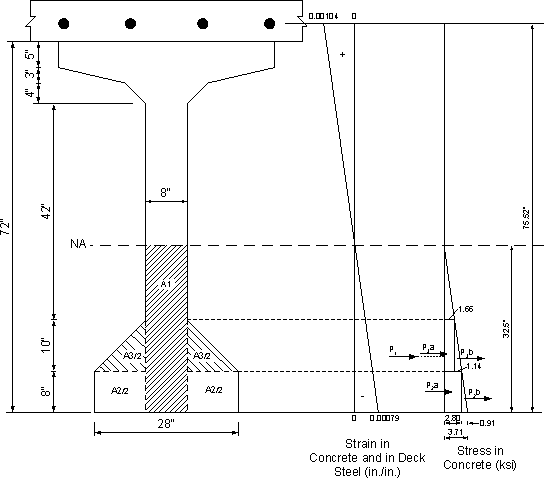
Referring to Figure 5.6-1:
Assume neutral axis at 32.5 inches from the bottom of beam
Assume maximum concrete compressive strain = 0.00079 in./in.
Tensile strain in deck reinforcement = 0.00079(75.52 - 32.5)/32.5 = 0.001046 in./in.
Modulus of elasticity of concrete beam = 4,696 ksi (see Section 2)
Concrete stress at bottom of beam = 0.00079(4,696) = 3.71 ksi
Area of deck longitudinal reinforcement = 14.65 in2 (see Section 5.6.5.1 for calculation)
Force in deck steel = 14.65(0.001046)(29,000) = 444.4 k
Force in prestressing steel = 797.2 k (see Table 5.5-1)
Compressive forces in the concrete:
Considering Figure 5.6-1, by calculating the forces acting on different areas as the volume of the stress blocks for areas A1, A2 and A3 as the volume of a wedge, prism or pyramid, as appropriate, the forces in Table 5.6-3 may be calculated. Recall that the centers of gravity of a wedge, a prism with all rectangular faces, a prism with a triangular vertical face and a pyramid are at one-third, one-half, one-third and one-quarter the height, respectively. The location of the centers of gravity shown in the figure may also be calculated. The moment from internal compressive concrete forces shown in Table 5.6-3 is equal to the force multiplied by the distance from the neutral axis to the location of the force.
Table 5.6-3 - Forces in Concrete Under Service Load in Negative Moment Regions (Section at 107'-3" from the end bearing)
Area
designation
Force
designation
Area
(in2)
Stress
(ksi)
Force
(kips)
Distance
from bot. of beam
(in)
Distance to N/A
(in)
Moment
at N/A
(k-ft)
A1 P1 260 3.71 482.3 10.83 21.67 871.0
A2 P2 a 160 2.80 448.0 4.00 28.50 1,064.0
A2 P2 b 160 0.91 72.8 2.67 29.83 181.0
A3 * P3 a 100 1.66 166.0 11.33 21.17 292.9
A3 * P3 b 100 1.14 76.0 10.50 22.00 139.3
Total       1,245.1     2,548.2
Figure showing the cross section of the beam and slab. The area that is in compression is noted and the stress and strain diagrams in the conpression area are given. Neutral axis shown, 32.5 inches from bottom of the girder. Girder total depth is 72 inches. Width thickness is 8 inches. Bottom flange width is 28 inches.
Figure 5.6-1 - Compressive Force in the Concrete
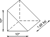
Figure showing how the rectangular stress distribution is calculated. This corresponds with Figure 5.6-1. Forces are shown as a prism for one area, with dimensions of the prism 10 inches and 10 inches for the triangular right angle base, with stress 1.66 ksi.
a) Rectangular Stress Distribution
Figure showing how the triangular stress distribution is calculated. This figure corresponds with Figure 5.6-1. For the second area with a pyramid distribution, the base of the triangle is 10 inches and 10 inches, and maximum stress is 1.14 ksi.
b) Triangular Stress Distribution
*Figure 5.6-1a - Shapes Used in Determining Forces for A3
Sample force calculations for area A3.
Two components of stress act on area A3. The first component is a rectangular stress distribution with an intensity of 1.66 ksi. The second component is a triangular stress distribution with an intensity of 1.14 ksi.
Force due to the rectangular stress distribution:

Frectangular    = 2[0.5(10)(10)](1.66)
= 166.0 k

The volume used to determine the effect of the triangular stress distribution is calculated using geometry of a pyramid.
Ftriangular    = 2 triangles(1/3 pyramid base)(pyramid height)
= 2(1/3)(10)(1.14)(10)
= 76.0 k

Check force equilibrium:

Net force on section    = P/S steel force + concrete compressive force + deck steel force
= 797.2 + (-1,245.1) + 444.4
= -3.5 kips ≈ 0 OK

Check moment equilibrium:

Net M on the section    = external moment + prestressing force moment + deck slab force moment + concrete compression moment
= 2,321 + 797.2(32.5 - 5.375)/12 - 444.4(75.52 - 32.5)/12 - 2,548.2
= -18.4 k-ft ≈ 0 OK
From Table 5.6-3, the maximum stress in the concrete is 3.71 ksi. The stress limit for compression under all loads (Table S5.9.4.2.1-1) under service condition is 0.6f′c (where f′c is the compressive strength of the girder concrete). For this example, the stress limit equals 3.6 ksi.
The calculated stress equals 3.71 ksi or is 3% overstressed. However, as explained above, the stress in the prestressing steel should decrease due to compressive strains in the concrete caused by external loads, i.e., prestressing steel force less than 797.2 k and the actual stress is expected to be lower than the calculated stress, and the above difference (3%) is considered within the acceptable tolerance.
Notice that the above calculations may be repeated for other cases of loading in Table S5.9.4.2.1-1 and the resulting applied stress is compared to the respective stress limit. However, the case of all loads applied typically controls.

Design Step 5.6.3 - Longitudinal steel at top of girder

The tensile stress limit at transfer used in this example requires the use of steel at the tension side of the beam to resist at least 120% of the tensile stress in the concrete calculated based on an uncracked section (Table S5.9.4.1.2-1). The sample calculations are shown for the section in Table 5.6-1 with the highest tensile stress at transfer, i.e., the section at 1.75 ft. from the centerline of the end bearing.
By integrating the tensile stress in Figure 5.6-2 over the corresponding area of the beam, the tensile force may be calculated as:
Tensile force    = 5(42)(0.451 + 0.268)/2 + 7.33(8.0)(0.268 + 0.0)/2 + 2[4(3)](0.268 +
   0.158)/2 + 2[4(4)/2][0.012 + (0.158 - 0.012)(2/3)] + 2[3(13)/2][0.158 +
   (0.268 - 0.158)(2/3)]
= 99.2 k

Required area of steel    = 1.2(99.2)/fy
= 119.0/60
= 1.98 in2

Required number of #5 bars    = 1.98/0.31
= 6.39 bars
Minimum allowable number of bars = 7 #5 bars
Use 8 #5 bars as shown in Figure 5.6-3
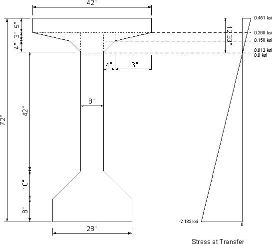
Figure showing the cross section of the beam and the associated stress diagram. The stress shown is at the location of maximum tensile stress at transfer.
Figure 5.6-2 - Stress at Location of Maximum Tensile Stress at Transfer
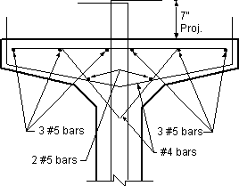
Figure showing the top third of the girder with all reinforcing bars.
Figure 5.6-3 - Longitudinal Reinforcement of Girder Top Flange

Design Step 5.6.4 - Flexural resistance at the strength limit state in positive moment region (S5.7.3.1)

Sample calculations at midspan

c = distance between the neutral axis and the compressive face at the nominal flexural resistance (in.)
c = 5.55 in., which is less than the slab thickness, therefore, the neutral axis is in the slab and section is treated as a rectangular section. (See Design Step 5.5.1 for commentary explaining how to proceed if "c" is greater than the deck thickness.)
fps    = stress in the prestressing steel at the nominal flexural resistance (ksi)
fps = 264.4 ksi
The factored flexural resistance, Mr, shall be taken as φMn, where Mn is determined using Eq. S5.7.3.2.2-1.
Factored flexural resistance in flanged sections (S5.7.3.2.2)
Mn = Apsfps(dp - a/2) + Asfy(ds - a/2) - A′sf′y(d′s - a/2) + 0.85f′c(b - bw1hf(a/2 - hf/2) (S5.7.3.2.2-1)
The definition of the variables in the above equation and their values for this example are as follows:
Aps    = area of prestressing steel (in2)
= 6.73 in2
fps = average stress in prestressing steel at nominal bending resistance specified in Eq. S5.7.3.1.1-1 (ksi)
= 264.4 ksi
dp = distance from extreme compression fiber to the centroid of prestressing tendons (in.)
= 74.5 in.
As = area of nonprestressed tension reinforcement (in2)
= 0.0 in2
fy = specified yield strength of reinforcing bars (ksi)
= 60 ksi
ds = distance from extreme compression fiber to the centroid of nonprestressed tensile reinforcement (in.), NA
A′s = area of compression reinforcement (in2)
= 0.0 in2
f′y = specified yield strength of compression reinforcement (ksi), NA
d′s = distance from the extreme compression fiber to the centroid of compression reinforcement (in.), NA
f′c = specified compressive strength of concrete at 28 days, unless another age is specified (ksi)
= 4.0 ksi (slab)
b = width of the effective compression block of the member (in.) = width of the effective flange
= 111 in. (See Design Step 5.5.1 for commentary for the determination of the effective width, b, when the calculations indicate that the compression block depth is larger than the flange thickness.)
bw = web width taken equal to the section width "b" for a rectangular section (in.), NA
β1 = stress block factor specified in S5.7.2.2, NA
hf = compression flange depth of an I or T member (in.), NA
a = β1c; depth of the equivalent stress block (in.)
= 0.85(5.55)
= 4.72 in.
The second, third and fourth terms in Eq. S5.7.3.2.2-1 are equal to zero for this example.
Substituting,
Mn    = 6.73(264.4)[74.5 - (4.72/2)]
= 128,367/12
= 10,697 k-ft
Therefore, the factored flexural resistance, Mr, shall be taken as:
Mr = φMn (S5.7.3.2.1-1) where:
φ    = resistance factor as specified in S5.5.4.2 for flexure in prestressed concrete = 1.0
Mr = 1.0(10,697 k-ft)
= 10,697 k-ft
The maximum factored applied moment for Strength I limit state is 8,456 k-ft (see Table 5.3-2)
Mr = 10,697 k-ft > Mu = 8,456 k-ft OK
Design Step 5.6.4.1 - Check if section is over-reinforced

Limits for reinforcing (S5.7.3.3)
The maximum amount of prestressed and nonprestressed reinforcement must be such that:
c/de    ≤ 0.42 (S5.7.3.3.1-1)
where:  
  c = 5.55 in. (see Section 5.5.1)

de = 74.5 in. (same as dp since no mild steel is considered)
c/de = 5.55/74.5
= 0.074 < 0.42 OK

Design Step 5.6.4.2 - Check minimum required reinforcement (S5.7.3.3.2)


Critical location is at the midspan of the continuous span = 55 ft. from the end bearing.
All strands are fully bonded at this location.
According to S5.7.3.3.2, unless otherwise specified, at any section of a flexural component, the amount of prestressed and nonprestressed tensile reinforcement shall be adequate to develop a factored flexural resistance, Mr, at least equal to the lesser of:
1.2 times the cracking strength determined on the basis of elastic stress distribution and the modulus of rupture, fr, on the concrete as specified in S5.4.2.6.
OR
1.33 times the factored moment required by the applicable strength load combinations specified in Table 3.4.1-1.
The cracking moment, Mcr, is calculated as the total moment acting on the beam when the maximum tensile stress equals the modulus of rupture.
fr = -Pt/Ag - Pte/Sb + MDNC/Sb + MDC/Sbc + M/Sbc
where:
MDNC    = factored using Service I limit state, see Table 5.3-1
= 3,511 k-ft
MDC = factored using Service I limit state, see Table 5.3-1
= 384 k-ft
Pt = fpfAstrandNstrands
= 1,096.2 k (from Table 5.6-2)
Ag = 1,085 in2
e54.5' = 31.38 in.
Sb = 20,157 in3
Sbc = 26,855 in3
fr f sub r equals 0.24 multiplied by square root of f prime c
0.24 multiplied by square root of 6
= 0.587 ksi (S5.4.2.6)
0.587 equals -1096.2 divided by 1085 minus 1096.2 times 31.38 divided by 20157 plus 3511 times 12 divided by 20157 plus 384 times 12 divided by 26855 plus M divided by 26855.
Solving for M, the additional moment required to cause cracking, in this equation:
M    = 27,983/12
2,332 k-ft
Mcr = MDNC + MDC + M
= 3,511 + 384 + 2,332
= 6,227 k-ft
1.2Mcr = 1.2(6,227)
= 7,472 k-ft
The applied factored moment, Mu, taken from Table 5.3-2 is 8,456 k-ft (Strength I)
1.33(8,456) = 11,246 k-ft
Mr has to be greater than the lesser of 1.2Mcr and 1.33Mu, i.e.,7,472 k-ft.
Mr also has to be greater than the applied factored load Mu = 8,456 k-ft (strength requirement)
Mr = 10,697 k-ft, therefore, both provisions are OK

Design Step 5.6.5 - Continuity connection at intermediate support


Design Step 5.6.5.1 - Negative moment connection at the Strength limit state
Determine the deck steel at the intermediate pier.
Based on preliminary calculations, the top and bottom longitudinal reinforcement of the deck are assumed to be #6 bars at 5.5 in. spacing and #6 bars at 8.5 in. spacing, respectively (see Figure 5.6-5).
Calculate the total area of steel per unit width of slab:
  As = Abar/spacing (in2/in.)
For top row of bars: As top    = 0.44/5.5
= 0.08 in2/in.
For bottom row of bars:    As bot = 0.44/8.5
= 0.052 in2/in.
Therefore, As = 0.08 + 0.052
= 0.132 in2/in.
Calculate the center of gravity of the slab steel from the top of the slab. Calculations are made from the top of the total thickness and include the integral wearing surface in the total thickness of slab. (See Figure 4-16)
Top mat (B1):    CGStop = Covertop + Dia#5 main rein. + ½ Dia#6
= 2.5 + 0.625 + ½ (0.75)
= 3.5 in.
Bot. mat (B2): CGSbot = tslab - Coverbot - Dia#5 main rein. - ½ Dia#6
= 8 - 1 - 0.625 - ½ (0.75)
= 6 in.
Center of gravity of the deck longitudinal reinforcement from the top of the deck:
CGS    = [As top(CGStop) + As bot(CGSbot)]/As
= [0.08(3.5) + 0.052(6)]/0.132
= 4.48 in. from the top of slab (3.98 in. from the top of the structural thickness)
Calculate the depth to the slab steel from the bottom of the beam. The haunch depth is ignored in the following calculations.
ds    = girder + slab - CGS
= 72 + 8 - 4.4
75.52 in.
The specification is silent about the strength of the concrete in the connection zone. Many jurisdictions use the girder concrete strength for these calculations. This reflects observations made during girder tests in the past. In these tests, the failure always occurred in the girder. This behavior is due to the confinement of the diaphragm concrete in the connection zone provided by the surrounding concrete. This confinement increases the apparent strength of the diaphragm concrete compared to the unconfined strength measured during typical testing of concrete cylinders.
Assume the neutral axis is in the bottom flange (rectangular behavior), therefore,
f′c    = f′c, beam = 6.0 ksi
β1 = β1, beam = 0.75 (corresponds to the 6.0 ksi concrete, S5.7.2.2)
b = width of section    = width of girder bottom flange = 28 in.
Calculate c,
c = Asfy/0.85β1f′cb (S5.7.3.1.1-4, modified)
where:
As    = area of reinforcement within the effective flange width of 111 in. (in2)
= Asbslab
= (0.132)(111)
= 14.65 in2
fy = 60 ksi
f′c = 6.0 ksi
β1 = 0.75
b = 28 in.
c    = 14.65(60)/[0.85(0.75)(6.0)(28)]
= 8.21 in., which is approximately equal to the thickness of the bottom flange of the beam (8 in.), therefore, the section is checked as a rectangular section. If "c" was significantly larger than the thickness of the bottom flange, a reduction in the section width should be considered.
Calculate the nominal flexural resistance according to S5.7.3.2.1 and the provisions for a rectangular section.
Mn = Asfy(ds - a/2)
where:
a    = β1c
= 0.75(8.21)
= 6.16 in.
ds = 75.52 in.
Mn    = 14.65(60)[75.52 - (6.16/2)]/12
= 5,306 k-ft
The factored flexural resistance, Mr, is
Mr = φfMn (S5.7.3.2.1-1)
where:
φf = 0.9 for flexure in reinforced concrete (S5.5.4.2.1)
Mr    = 0.9(5,306)
= 4,775 k-ft

Check moment capacity versus the maximum applied factored moment at the critical location
Critical location is at the centerline of pier.
Strength I limit state controls.
|Mu| = 4,729 k-ft (see Table 5.3-2) < Mr = 4,775 k-ft OK
Check service crack control (S5.5.2)
Actions to be considered at the service limit state are cracking, deformations, and concrete stresses, as specified in Articles S5.7.3.4, S5.7.3.6, and S5.9.4, respectively. The cracking stress is taken as the modulus of rupture specified in S5.4.2.6.
Components shall be so proportioned that the tensile stress in the mild steel reinforcement at the service limit state does not exceed fsa, determined as:
fsa = Z/(dcA)1/3 ≤ 0.6fy = 0.6(60) = 36 ksi where:
Z    = crack width parameter (kip/in.)
= 170 kip/in. (for members in moderate exposure conditions; the example bridge is located in a warm climate (Atlanta) where the use of deicing salts is possible, but not likely)
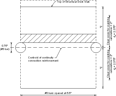
dc = depth of concrete measured from extreme tension fiber to center of bar or wire located closest thereto (in.); for calculation purposes, the thickness of clear cover used to compute dc shall not be taken to be greater than 2.0 in.
= concrete cover + ½ secondary rein.
= 2.0 + ½ (0.75) = 2.375 in. (see Figure 5.6-4)
A = area of concrete having the same centroid as the principal tensile reinforcement and bounded by the surfaces of the cross-section and a straight line parallel to the neutral axis, divided by the number of bars or wires (in2); for calculation purposes, the thickness of clear concrete cover used to compute "A" shall not be taken to be greater than 2.0 in.
= [2(2.0) + 0.75]5.5/1 bar = 26.125 in2/bar (see Figure 5.6-4)
Continuity connection. Centerline of continuity connection bars is 3 inches from the bottom of the section and 3 inches from the top of the structural deck slab section. Bars are No. 6 placed at 5-1/2 inches spacing.
Figure 5.6-4 - Dimensions for Calculation of the Area, A
fsa    = 170/[2.375(26.125)]1/3
= 42.94 ksi > 0.6fy = 36 ksi, therefore, use fsa = 36 ksi
Connection moment at Service I limit state is 2,858 k-ft (see Table 5.3-2)
Assuming:    Section width is equal to beam bottom flange width = 28 in
Modular ratio = 6 for 6 ksi concrete
Area of steel = 14.65 in2
At service limit state, the depth of the neutral axis and the transformed moment of inertia under service loads may be calculated using the same procedure used earlier in the example (Section 4). The neutral axis is 18.86 in. from the bottom of the beam.
Maximum service stress in the steel = 33.74 ksi < 36 ksi OK
Design Step 5.6.5.2 - Positive moment connection
For jurisdictions that consider creep and shrinkage in the design, it is likely that positive moment will develop at intermediate piers under the effect of prestressing, permanent loads and creep and shrinkage. These jurisdictions provide reinforcement at the bottom of the beams at intermediate diaphragms to resist the factored positive moment at these locations.
For jurisdictions that do not consider creep and shrinkage in the design, it is unlikely that live load positive moments at intermediate supports will exceed the negative moments from composite permanent loads at these locations. This suggests that there is no need for the positive moment connection. However, in recognition of the presence of creep and shrinkage effects, most jurisdictions specify some reinforcement to resist positive moments.
Two forms of the connection have been in use:
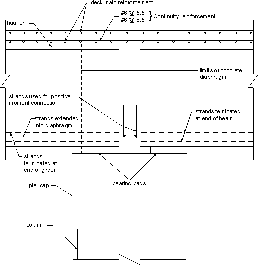
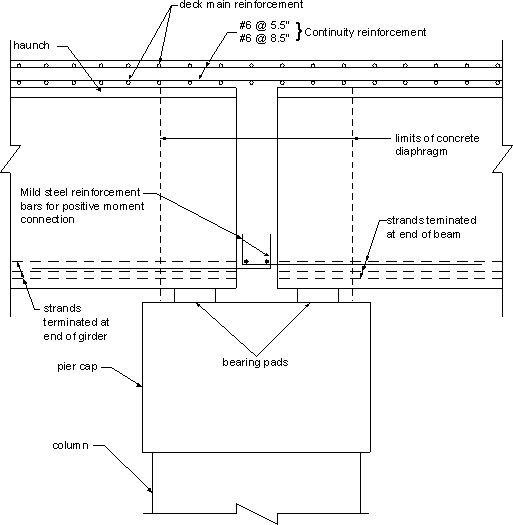
  • Figure 5.6-5 shows one alternative that requires extending some of the prestressing strands at the end of the girder into the intermediate diaphragm. Due to the small space between girders, these strands are bent upwards into the diaphragm to provide adequate anchorage. Only strands that are fully bonded are used for the positive moment connection.
  • The second alternative requires adding mild reinforcement bars as shown in Figure 5.6-6. This alternative may lead to congestion at the end of the beam due to the presence of the prestressing strands at these locations.
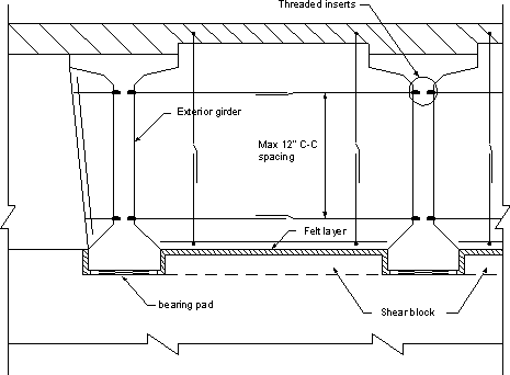
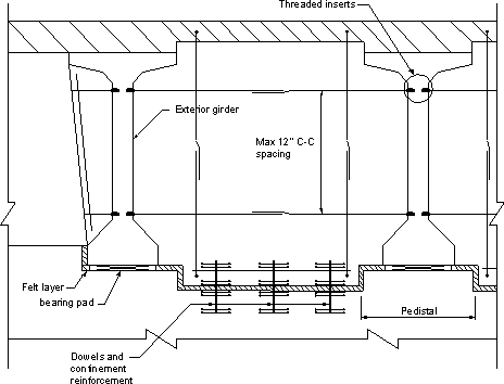
Typical details of the top of the pier cap for expansion and fixed bearings are shown schematically in Figures 5.6-7 and 5.6-8.
Figure showing the continuity connection at the intermediate pier (alternative one). The beam prestressing strands extend outside of the beam and are bent up in the concrete diaphragm region.
Figure 5.6-5 - Continuity Connection Alternative 1: Strands Used for Positive Moment Connection
Figure showing mild reinforcement placed inside the end of the beam extending outside of the beam ends and bent up in the concrete diaphragm region.
Figure 5.6-6 - Continuity Connection Alternative 2: Reinforcement Bars Used for Positive Moment Connection
Figure showing an expansion bearing. Two beams are resting on bearing pads with shear blocks inbetween the bottom flanges. A concrete diaphragm is poured between the girders at the intermediate support. Vertical and horizontal reinforcement is provided in the concete diaphragm.
Figure 5.6-7 - Typical Diaphragm at Intermediate Pier (Expansion Bearing)
Figure showing two beams resting on bearing pads. Vertical and horizontal reinforcement is provided for encasement in the concrete diaphragm. Dowels and confinement reinforcement are provided to created a fixed bearing at the intermediate pier.
Figure 5.6-8 - Typical Diaphragm at Intermediate Pier (Fixed Bearing)

Design Step 5.6.6 - Fatigue in prestressed steel (S5.5.3)

Article S5.5.3 states that fatigue need not be checked when the maximum tensile stress in the concrete under Service III limit state is taken according to the stress limits of Table S5.9.4.2.2-1. The stress limit in this table was used in this example and, therefore, fatigue of the prestressing steel need not be checked.

Design Step 5.6.7 - Camber (S5.7.3.6)

The provisions of S2.5.2.6 shall be considered.
Deflection and camber calculations shall consider dead load, live load, prestressing, erection loads, concrete creep and shrinkage, and steel relaxation. For determining deflection and camber, the provisions of Articles S4.5.2.1, S4.5.2.2, and S5.9.5.5 shall apply.
Instantaneous deflections are computed using the modulus of elasticity for concrete as specified in S5.4.2.4 and taking the gross moment of inertia, Ig,as allowed by S5.7.3.6.2.
Deflection values are computed based on prestressing, girder self-weight, slab, formwork, exterior diaphragm weight, and superimposed dead load weight. Camber values are computed based on initial camber, initial camber adjusted for creep, and final camber. Typically, these calculations are conducted using a computer program. Detailed calculations are presented below.
Deflection due to initial prestressing is computed as:
ΔP/S = -(PtesL2)/(8EciIg) (for straight bonded strands)
ΔP/S = -Ptes[L2 - (Lt + 2Lx)2]/(8EciIg) (for debonded strands)
where:
Pt    = applied load acting on the section (kips)
es = eccentricity of the prestressing force with respect to the centroid of the cross section at the midspan of the beam (in.)
L = span length (ft.)
Lt = transfer length of the strands (in.)
Lx = distance from end of beam to point where bonding commences (in.)
Eci = modulus of elasticity of concrete at transfer (ksi)
Ig = moment of inertia (in4)
The negative sign indicates upward deflection.
Computer software is generally used to determine the deflections due to each loading. However, sample calculations are provided for this example.
See Table 5.5-1 for prestressing forces.
Group 1 strands:    32 fully bonded strands
Initial prestressing force = 924.4 k
Distance from bottom of the beam to the neutral axis = 36.38 in.
Distance from the bottom of the beam to the centroid of Group 1 strands = 5.375 in.
Deflection due to Group 1 strands:
ΔP/S 1    = -(PtesL2)/(8EciIg)
= -[924.4(36.38 - 5.375)[109(12)]2]/[8(4,200)(733,320)]
= -1.99 in. (upward deflection)

Group 2 strands:    6 strands debonded for 10 ft. from centerline of bearings
Transfer length = 30 in.
Initial prestressing force = 173.3 k
From Figures 2-5 and 2-6, the distance from the bottom of the beam to the centroid of Group 2 is 4.0 in.
Deflection due to Group 2 strands:
ΔP/S 2    = -Ptes[L2 - (Lt + 2Lx)2]/(8EciIg)
= -173.3(36.38 - 4.0)[[109(12)]2 - [30 + 2(10)(12)]2]/[8(4,200)(733,320)]
= -0.37 in. (upward deflection)

Group 3 strands:    6 strands debonded for 22 ft. from centerline of bearings
Transfer length = 30 in.
Initial prestressing force = 173.3 k
From Figures 2-5 and 2-6, the distance from the bottom of the beam to the centroid of Group 3 is 4.0 in.
Deflection due to Group 3 strands:
ΔP/S 3    = -Ptes[L2 - (Lt + 2Lx)2]/(8EciIg)
= -173.3(36.38 - 4.0)[[109(12)]2 - [30 + 2(22)(12)]2]/[8(4,200)(733,320)]
= -0.32 in. (upward deflection)
Total initial deflection due to prestressing:
ΔP/S Tot    = -1.99 - 0.37 - 0.32
= -2.68 in. (upward deflection)
Notice that for camber calculations, some jurisdictions assume that some of the prestressing force is lost and only consider a percentage of the value calculated above (e.g. Pennsylvania uses 90% of the above value). In the following calculations the full value is used. The user may revise these values to match any reduction required by the bridge owner's specification.
Using conventional beam theory to determine deflection of simple span beams under uniform load or concentrated loads and using the loads calculated in Section 5.2, using noncomposite and composite girder properties for loads applied before and after the slab is hardened, respectively, the following deflections may be calculated:
Δsw    = deflection due to the girder self-weight
= 1.16 in.
Δs = deflection due to the slab, formwork, and exterior diaphragm weight
= 1.12 in.
ΔSDL = deflection due to the superimposed dead load weight
= 0.104 in.
All deflection from dead load is positive (downward).
Design Step 5.6.7.1 - Camber to determine bridge seat elevations
Initial camber, Ci:
Ci    = ΔP/S Tot + Δsw
= -2.68 + 1.16
= -1.52 in. (upward deflection)
Initial camber adjusted for creep, CiA:
Cr    = constant to account for creep in camber (S5.4.2.3.2)
3.5 times k sub c times k sub f times the quantity 1.58 minus H divided by 120 end quantity times t sub i raised to the -0.118 times the quantity t minus t sub i quantity raised to the 0.6 divided by the quantity 10 plus the quantity t minus t sub i end quantity raised to the 0.6 end quantity . (S5.4.2.3.2-1
kc = factor for the effect of the volume-to-surface area ratio of the component as specified in Figure S5.4.2.3.2-1.
In order to determine kc, the volume-to-surface area ratio needs to be calculated. See Figure 2-3 for girder dimensions.
Beam area = 1,085 in2
Beam volume    = 1,085(12)
= 13,020 in3/ft
Surface area = 2,955.38 in2/ft
(V/S)b = 13,020/2,955.38
= 4.406 in.
Using Figure S5.4.2.3.2-1 or SC5.4.2.3.2-1, the correction factor, kc, is taken to be approximately 0.759.
kf    = factor for the effect of concrete strength
 1 divided by the quantity of 0.67 plus f prime sub c divided by 9 end quantity. (S5.4.2.3.2-2)
1 divided by the quantity of 0.67 plus 6 divided by 9 end quantity.
H = relative humidity from Figure S5.4.2.3.3-1
= 70%
ti = age of concrete when load is initially applied
= 1 day
t = maturity of concrete
= infinite
Cr = 3.5(0.759)(0.748)[1.58 - (70/120)](1)-0.118
= 1.98
Therefore, the initial camber, CiA is:
CiA    = -1.52(1.98)
= -3.01 in. (upward deflection)
Final camber, CF:
CF    = CiA + Δs + ΔSDL
= -3.01 + 1.12 + 0.104
= -1.79 in. (upward deflection)
This camber is used to determine bridge seat elevation.
Design Step 5.6.7.2 - Haunch thickness
The haunch thickness is varied along the length of the girders to provide the required roadway elevation. For this example, the roadway grade is assumed to be 0.0. Therefore, the difference between the maximum haunch thickness at the support and the minimum haunch thickness at the center of the beam should equal the final camber, i.e., 1.79 in. in this example. Minimum haunch thickness is not included in the specifications and is typically specified by the bridge owner. Figure 5.6-9 shows schematically the variation in haunch thickness. Haunch thickness at intermediate points is typically calculated using a computer program.
Figure showing a cambered beam with the roadway elevation shown as well.
Figure 5.6-9 - Schematic View of Haunch
Design Step 5.6.7.3 - Camber to determine probable sag in bridge
To eliminate the possibility of sag in the bridge under permanent loads, some jurisdictions require that the above calculations for CF be repeated assuming a further reduction in the initial P/S camber. The final CF value after this reduction should show upward deflection.

Design Step 5.6.8 - Optional live load deflection check

Service load deformations may cause deterioration of wearing surfaces and local cracking in concrete slabs and in metal bridges which could impair serviceability and durability, even if self limiting and not a potential source of collapse.
As early as 1905, attempts were made to avoid these effects by limiting the depth-to-span ratios of trusses and girders, and starting in the 1930's, live load deflection limits were prescribed for the same purpose. In a study of deflection limitations of bridges ASCE (1958), an ASCE committee, found numerous shortcomings in these traditional approaches and noted them. For example:
"The limited survey conducted by the Committee revealed no evidence of serious structural damage that could be attributed to excessive deflection. The few examples of damaged stringer connections or cracked concrete floors could probably be corrected more effectively by changes in design than by more restrictive limitations on deflection. On the other hand, both the historical study and the results from the survey indicate clearly that unfavorable psychological reaction to bridge deflection is probably the most frequent and important source of concern regarding the flexibility of bridges. However, those characteristics of bridge vibration which are considered objectionable by pedestrians or passengers in vehicles cannot yet be defined."
Since that time, there has been extensive research on human response to motion, and it is now generally agreed that the primary factor affecting human sensitivity is acceleration as opposed to deflection, velocity, or the rate of change of acceleration for bridge structures, but the problem is a difficult subjective one. Thus, to this point in history there are no simple definitive guidelines for the limits of tolerable static deflection or dynamic motion. Among current specifications, the Ontario Highway Bridge Design Code of 1983 contains the most comprehensive provisions regarding vibrations tolerable to humans.
The deflection criteria in S2.5.2.6.2 is considered optional. The bridge owner may select to invoke this criteria if desired. If an Owner chooses to invoke deflection control, the following principles may apply:
  • when investigating the maximum absolute deflection, all design lanes should be loaded, and all supporting components should be assumed to deflect equally,
  • for composite design, the design cross-section should include the entire width of the roadway and the structurally continuous portions of the railings, sidewalks and median barriers
  • when investigating maximum relative displacements, the number and position of loaded lanes should be selected to provide the worst differential effect,
  • the live load portion of load combination Service I of Table S3.4.1-1 should be used, including the dynamic load allowance, IM
  • the live load shall be taken from S3.6.1.3.2,
  • the provisions of S3.6.1.1.2 should apply,
  • for skewed bridges, a right cross-section may be used; for curved and curved skewed bridges a radial cross-section may be used.
If the Owner invokes the optional live load deflection criteria, the deflection should be taken as the larger of:
  • That resulting from the design truck alone, or
  • That resulting from 25 percent of the design truck taken together with the design lane load.
According to S2.5.2.6.2, the deflection criteria for vehicular live load limits deflection to L/800.
110(12)/800 = 1.65 in.
The calculated live load deflection determined by using computer software is 0.324 in.
0.324 in. < 1.65 in. OK