- -The beam is originally straight, and any taper is slight
- -The beam experiences only linear elastic deformation
- -The beam is slender (its length to height ratio is greater than 10)
- -Only small deflections are considered (max deflection less than 1/10 the span.
 ) can be approximated as:
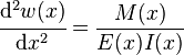
 is interpreted as its curvature,
  is the Young's modulus,
  is the area moment of inertia of the cross-section, and
  is the internal bending moment in the beam.
If, in addition, the beam is not tapered and is homogeneous, and is acted upon by a distributed load
 , the above expression can be written as:
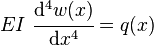
Cantilever beams
Cantilever beams have one end fixed, so that the slope and deflection at that end must be zero.
Schematic of the deflection of a cantilever beam.
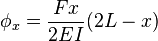
End-loaded cantilever beams

Cantilever beam with a force on the free end
 and angle of deflection
  (in radians) at the free end in the example image: A (weightless) cantilever beam, with an end load, can be calculated (at the free end B) using:[1]

 = Force acting on the tip of the beam
 = Length of the beam (span)
- = Modulus of elasticity
- = Area moment of inertia of the beam's cross section
, along the span of an end loaded cantilevered beam can be calculated using:[1]
 (the end of the beam), the
  and
and  equations are identical to the
  and
and  equations above.
Uniformly-loaded cantilever beams

Cantilever beam with a uniform distributed load


- = Uniform load on the beam (force per unit length)
- = Length of the beam
- = Modulus of elasticity
- = Area moment of inertia of cross section
, along the span of a uniformly loaded cantilevered beam can be calculated using:[1]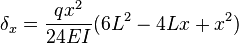
Simply-supported beams
Simply-supported beams have supports under their ends which allow rotation, but not deflection.
Schematic of the deflection of a simply-supported beam.
Center-loaded simple beams

Simply-supported beam with a force in the center

- = Force acting on the center of the beam
- = Length of the beam between the supports
- = Modulus of elasticity
- = Area moment of inertia of cross section
, along the span of a center loaded simply supported beam can be calculated using:[1]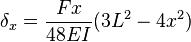

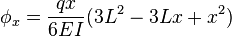
Off-center-loaded simple beams

Simply-supported beam with a force off center
 from the closest support, is given by:[1]
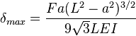
- = Force acting on the beam
- = Length of the beam between the supports
- = Modulus of elasticity
- = Area moment of inertia of cross section
- = Distance from the load to the closest support (i.e.
 )
)
 from the closest support and is given by:[1]
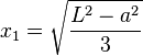
Uniformly-loaded simple beams

Simply-supported beam with a uniform distributed load

- = Uniform load on the beam (force per unit length)
- = Length of the beam
- = Modulus of elasticity
- = Area moment of inertia of cross section
, along the span of a uniformly loaded simply supported beam can be calculated using:[1]
Units
The formulas supplied above require the use of a consistent set of units. Most calculations will be made in SI or US customary units, although there are many other systems of units.International system (SI)
- Force: newtons (
 )
)
 )
)- Modulus of elasticity:

- Moment of inertia:

US customary units (US)
- Force: pounds force (
 )
) - Length: inches (
 )
) - Modulus of elasticity:

- Moment of inertia:

Others
Other units may be used as well, as long as they are self-consistent. For example, sometimes the kilogram force ( ) unit is used to measure loads. In such a case, the modulus of elasticity must be converted to
  .
.
No comments:
Post a Comment